


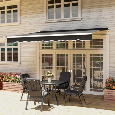


The Outsunny Outdoor Table (SKU:84B-020) is a durable and stylish addition to any patio, garden, balcony, or outdoor seating area. Built with a stable steel frame and a wide tabletop, it offers reliable support for meals, decor, beverages, and outdoor gatherings. Its curved legs, reinforced center bracket, and scratch-resistant surface ensure long-lasting use in all weather conditions.
Before You Begin
Estimated Assembly Time: 20–35 minutes
Recommended Personnel: 1–2 adults
Assembly Surface: Use a flat, soft surface to prevent scratching the tabletop or bending any metal components.
Important Notes
- Do not confuse similar screws, check each label carefully before assembly.
- Do not fully tighten bolts until all parts are connected, to ensure proper alignment.
- Keep small hardware pieces away from children and pets.
- Ensure all washers (flat & spring) are used exactly as shown in diagrams for safety and stability.
Parts & Hardware
Parts List
| Label | Quantity | Name / Description |
| A | 4 | Curved Support Bars |
| B | 4 | Rectangular Side Frames (with pre-drilled holes) |
| C | 1 | Top Panel / Table Surface |
Hardware List
| Label | Quantity | Name / Description |
| D | 1 | Wrench / Spanner |
| E | 16 (+1 spare) | M8 × 35 Bolts |
| F | 16 (+1 spare) | Flat Washers |
| G | 16 (+1 spare) | Spring Washers |
| H | 16 (+1 spare) | Hex Nuts |
| I | 1 | Allen Key / Hex Key |
Assembly Instructions
Follow these steps carefully and proceed sequentially to assemble your Outsunny Outdoor Table (SKU:84B-020)
Step 1: Prepare and Position the Rectangular Side Frames
In this step, you will need
- Rectangular Side Frames – B (x4)
Instructions:
- Place one Rectangular Side Frame (B) onto your assembly surface.
- Make sure the frame is oriented correctly: the angled edges must face upward, exactly as shown in the diagram. This allows the Curved Support Bars to attach properly in the next steps.
- Verify all four Rectangular Side Frames (B) are positioned with the correct angle direction before proceeding to Step 2.
Guide:
- The ✓ icon shows the correct angle direction.
- The X icons show incorrect orientations that may cause misalignment.
Step 2: Attach the Curved Support Bars
In this step, you will need:
- Curved Support Bar – A (x1)
- M8×35 Bolts – E (x2)
- Allen Key – I (x1)
Instructions:
- Place one Curved Support Bar (A) on your assembly surface.
- Align the pre-drilled holes on the bar with the mounting holes shown in the diagram.
- Insert two M8×35 Bolts (E) into the holes.
- Use the Allen Key (I) to tighten the bolts until they are snug, but do not fully tighten yet, final adjustments will be made once the frame is assembled.
- Repeat this process for all four Curved Support Bars (A).
Step 3: Connect the Rectangular Side Frames to the Curved Support Bar
In this step, you will need:
- Rectangular Side Frames – B (x2)
- Flat Washers – F (x2)
- Spring Washers – G (x2)
- Hex Nuts – H (x2)
- Wrench – D (x1)
Instructions:
- Position two Rectangular Side Frames (B) above the mounted Curved Support Bar (A), aligning the holes on both components.
- Slide one Flat Washer (F) onto each exposed bolt coming through the frame.
- Next, place one Spring Washer (G) on top of each flat washer.
- Secure both joints by threading a Hex Nut (H) onto each bolt by hand.
- Use the Wrench (D) to tighten the nuts until snug, but do not fully tighten yet, final adjustments will be made once all frame connections are complete.
Step 4: Attach the Remaining Curved Support Bar to the Side Frames
In this step, you will need:
- Curved Support Bar – A (x1)
- Rectangular Side Frames – B (already attached from previous step)
- Flat Washers – F (x2)
- Spring Washers – G (x2)
- Hex Nuts – H (x2)
- Wrench – D (x1)
Instructions:
- Position the second Curved Support Bar (A) beneath the assembled Rectangular Side Frames (B), aligning the mounting holes on both components.
- Slide one Flat Washer (F) onto each exposed bolt.
- Place one Spring Washer (G) on top of each flat washer to maintain tension and prevent loosening.
- Thread a Hex Nut (H) onto each bolt by hand.
- Use the Wrench (D) to tighten the nuts until snug, but do not fully tighten, final adjustments will be made after the entire frame is assembled.
Step 5: Secure the Remaining Curved Support Bars to the Frame
In this step, you will need:
- Curved Support Bars – A (x2)
- Flat Washers – F (x2)
- Spring Washers – G (x2)
- Hex Nuts – H (x2)
- Wrench – D (x1)
Instructions:
- Position the final two Curved Support Bars (A) onto the open sides of the assembled Rectangular Side Frames (B), aligning all mounting holes as shown in the diagram.
- Slide one Flat Washer (F) onto each exposed bolt coming through the side frames.
- Place one Spring Washer (G) on top of each flat washer.
- Thread a Hex Nut (H) onto each bolt by hand to hold the components in place.
- Use the Wrench (D) to tighten both nuts until they are snug, completing the full leg-frame structure.
- Do not fully tighten all frame connections yet final balancing will be done after attaching the tabletop.
Step 6: Prepare the Top Panel for Installation
In this step, you will need:
- Top Panel – C (x1)
- M8×35 Bolts – E (x8)
- Allen Key – I (x1)
Instructions:
- Place the Top Panel (C) upside down on a soft, flat surface to prevent scratches.
- Locate the eight pre-drilled mounting holes on the underside of the panel.
- Insert one M8×35 Bolt (E) into each hole, positioning all eight bolts vertically as shown in the diagram.
- Use the Allen Key (I) to tighten each bolt until snug.
- Ensure all bolts are evenly inserted and standing straight, this will make it easier to align the tabletop with the frame in the next step.
Step 7: Attach the Frame to the Top Panel
In this step, you will need:
- Flat Washers – F (x8)
- Spring Washers – G (x8)
- Hex Nuts – H (x8)
- Wrench – D (x1)
- (Top Panel – C and full leg frame are used from previous steps)
Instructions:
- Carefully place the assembled leg frame upside down onto the Top Panel (C), aligning all eight bolts with the holes in the Curved Support Bars (A).
- For each bolt:
- Slide a Flat Washer (F) onto the bolt first.
- Next, add a Spring Washer (G) to help maintain tension during use.
- Finally, thread a Hex Nut (H) onto each bolt by hand.
- Once all washers and nuts are in place, use the Wrench (D) to tighten each nut gradually in a cross-pattern.
- After all eight nuts are snug, go back and fully tighten every connection on the table, including the joints from earlier steps.
- Confirm the legs are level and the table sits evenly on the ground before turning it upright.
Final Step: Level the Table and Complete Assembly
Instructions:
- Carefully turn the table upright and place it on a flat, stable surface.
- Check if the table stands evenly. If any leg is slightly higher or lower, adjust the leveling foot located at the bottom of each Curved Support Bar (A).
- Rotate each leveling foot clockwise or counter-clockwise until the table sits flat and stable with no wobbling.
- Once the table is level, your assembly is complete.
Your Outsunny Outdoor Table (SKU: 84B-020) is now fully assembled and ready for use. Enjoy a sturdy and stylish addition to your outdoor space.
Safety Precautions
- Assemble the table on a flat, stable surface to prevent misalignment or wobbling.
- Keep children and pets away during assembly to avoid accidents.
- Do not lean, sit, or stand on the tabletop or curved legs.
- Ensure all bolts, washers, and nuts are fully tightened before using the table.
- Check stability regularly, especially after moving the table or adjusting the leveling feet.
- Avoid exceeding the tabletop’s weight capacity.
Care & Maintenance
- Cleaning: Wipe the tabletop and frame with a soft, damp cloth. Avoid using harsh cleaners, abrasive pads, or chemicals that may damage the finish.
- Outdoor Protection: Although the table is designed for outdoor use, storing it indoors during extreme weather (heavy rain, snow, or strong sun exposure) will extend its lifespan.
- Maintenance: Periodically check all screws, washers, and nuts to ensure they remain tight. Temperature changes and outdoor use may gradually loosen hardware over time.
- Surface Care: Do not place extremely hot items directly on the tabletop. Use coasters or mats to prevent damage.
You can also download a copy of the Outsunny Outdoor Table (SKU: 84B-020) Manual(PDF) for future reference.
For technical support, replacement parts, or product questions,contact Aosom LLC’s Customer Service and get friendly assistance.
FAQs
1. How do I tighten the hardware if it becomes loose over time?
Use the included wrench and Allen key to retighten the bolts and nuts. Outdoor temperature changes can loosen hardware, so periodic checks are helpful.
2. What if the tabletop does not sit flush on the frame?
This usually happens when the frame bolts were tightened too early. Loosen the frame joints slightly, reposition the frame on the tabletop, and retighten the nuts in sequence to ensure even pressure.
3. What if the bolts do not align with the holes during assembly?
Do not force the bolts in. Loosen the surrounding connections slightly to allow the frame to shift into place. Once all bolts slide in easily, tighten each connection gradually in a balanced, cross-pattern.